
The compatibility chain
The drive path normally includes the motor or linear-drive component, controller, feedback or position information, power supply, mechanical transmission, hangers or arms and the moving door. A mismatch at any point can appear as noise, poor learning, unstable speed, repeated faults, excess heating or incomplete travel.
For a replacement, photograph the existing nameplate, controller, terminals, connectors, transmission, installation dimensions and full operator assembly. Record the fault symptoms before disconnecting parts. Similar-looking motors may use different feedback, voltage, connectors or control logic.
Inputs for a new selection
- Sliding, swing, telescopic or other door layout
- Number of moving leaves and finished mass per leaf
- Required travel and available operator length
- Target opening and closing behavior
- Expected cycles and operating environment
- Transmission or direct-drive arrangement
- Controller, sensors, locks and access-control interfaces
- Power supply and power-loss behavior
Read parameters in context
Rated power, torque or force, voltage, speed and duty values are meaningful only with the manufacturer's definitions and test conditions. A larger number is not automatically a better door. Excess drive capacity cannot correct a binding guide, misaligned track, unsuitable transmission or an incompatible controller.
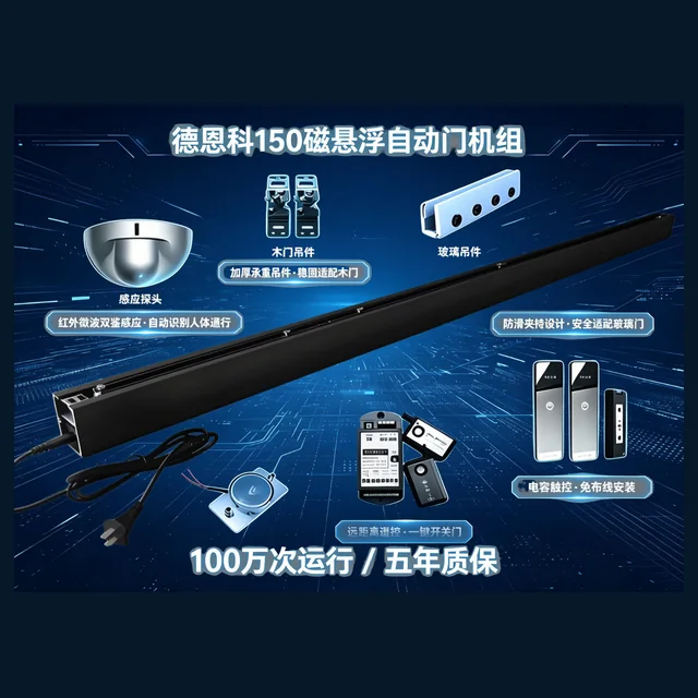
For magnetic levitation systems, also identify the mover or stator arrangement, controller version, feedback method, compatible track or hardware and any required learning procedure. Keep the bill of materials tied to one documented configuration.
Replacement diagnosis before ordering
| Observed issue | Check before replacing the motor |
|---|---|
| No movement | Supply, protection, controller state, inputs, lock and wiring |
| Jerky motion | Mechanical resistance, feedback, setup, transmission and connectors |
| Noise | Track, rollers, guides, belt or gearing, fasteners and leaf contact |
| Heating | Duty, binding, supply, settings, load and ventilation |
| Stops early | Obstruction inputs, limits, learned travel, sensor zones and guides |
Acceptance for a motor or operator assembly
Verify model and connector identification before installation. After mechanical alignment, run the documented setup process and observe repeated full travel. Test activation, safety sensing, obstruction response, hold-open modes, lock interaction and power-loss recovery as applicable.
Record the final parameter set, controller and motor identifiers, connected accessories, wiring changes and fault history. These records make later service more reliable than a generic “motor replaced” note.